Network model
The TCP/IP five network model
| Layer | Protocal | Content | Address | |
|---|---|---|---|---|
| 5 | Application | HTTP, SMTP, etc… | Message | n/a |
| 4 | Transport | TCP/UDP | Segment | Port #’s |
| 3 | Network | IP | Packet/Datagram | IP Address |
| 2 | Data Link | Ethernet, Wi-Fi | Frames | MAC address |
| 1 | Physical | n/a | Bits | n/a |
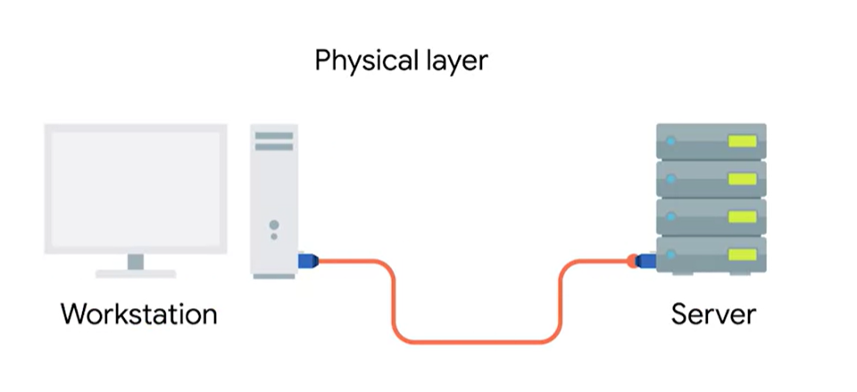
Physical layer
Define: Represents the physical devices that interconnect computers
The physical layer consists of devices and means of transmitting bits across computer networks.
A bit is the smallest representation of data that a computer can understand. It’s zero or one.
These ones and zeros sense across networks at the lowest level are what make up the frames and packets of data that we’ll learn about when we cover the other layers.
Modulation
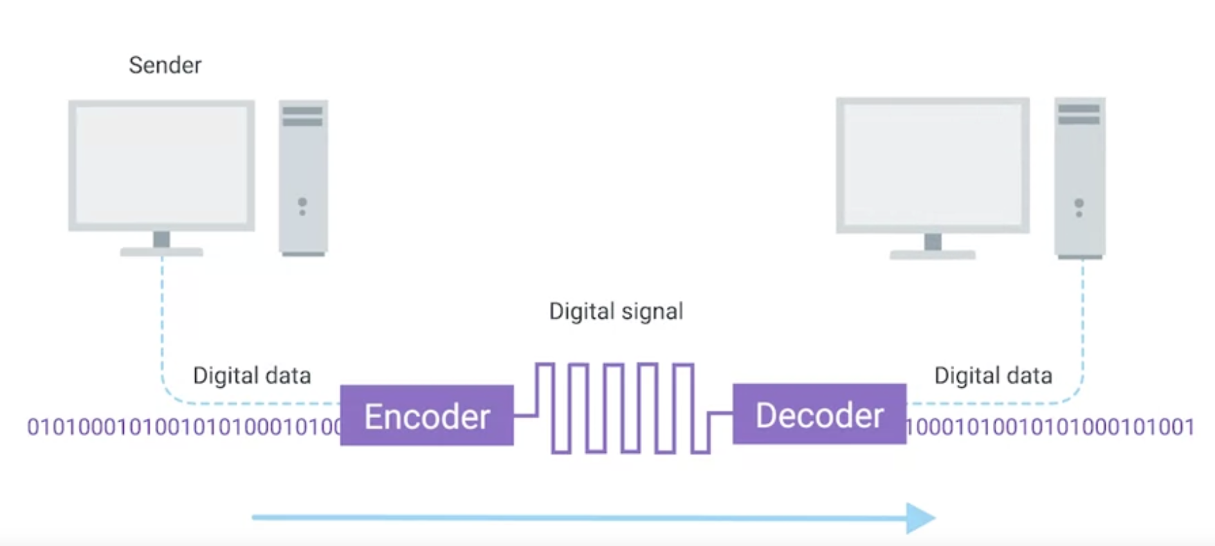
Ones and zeros are sent across those network cables through a process called modulation.
Modulation is a way of varying the voltage of this charge moving across the cable. When used for computer networks, this kind of modulation is more specifically known as line coding.
It allows devices on either end of a link to understand that an electrical charge in a certain state is a zero and another state is one.
Through this seemingly simple technique, modern networks are capable of moving 10 billion ones and zeros across a single network cable every second.
Twisted pair cabling and duplexing
- Twisted pair cabling is the most common type for connecting computing devices.
- It consists of pairs of copper wires twisted together to protect against interference.
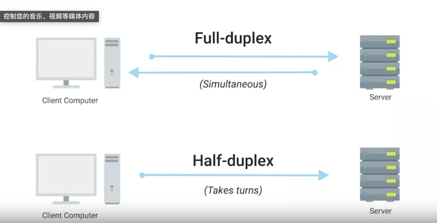
- These cables allow for duplex communication, meaning information can flow in both directions.
- Full duplex allows devices to communicate simultaneously in both directions.
- Half-duplex means communication is possible in both directions, but only one device can communicate at a time.
Why twisted?
Originally, telephone and early data cables included two copper wires, one for transmissiontting data and one for receiving data. The two wires laid parallel to one another.
This configuration was affected by electromagneticgnetic interference(EMI), radio frequency interference(RFI), and crosstalk between the two copper wires.
One of the initial engineering steps to resolve these issues involved twisting the wire pair together, which reduce some of the extra noise on the lines.
Data link layer
Define: Responsible for defining a common way of interpreting these signals so network devices can communicate.
The Ethernet standards also define a protocol responsible for getting data to nodes on the same network or link.
The protocol most widely used to send data across individual links is known as ethernet. Ethernet and the data link layer provide a means for software at higher levels of the stack to send and receive data.
Data link layer what used for?
One of the primary purposes of this layer is to essentially abstract away the need for any other layers to care about the physical layer and what hardware is in use.
For example, your web browser dosen’t need to know if it’s running on a device connected via twisted pair or wireless connection, it just need the underlying layers to send and receive data for it.
What Ethernet do?
Background: A collision domain is a network segment where only one device can speak at a time. This is because all data in a collision domain is sent to all the nodes connected to it.
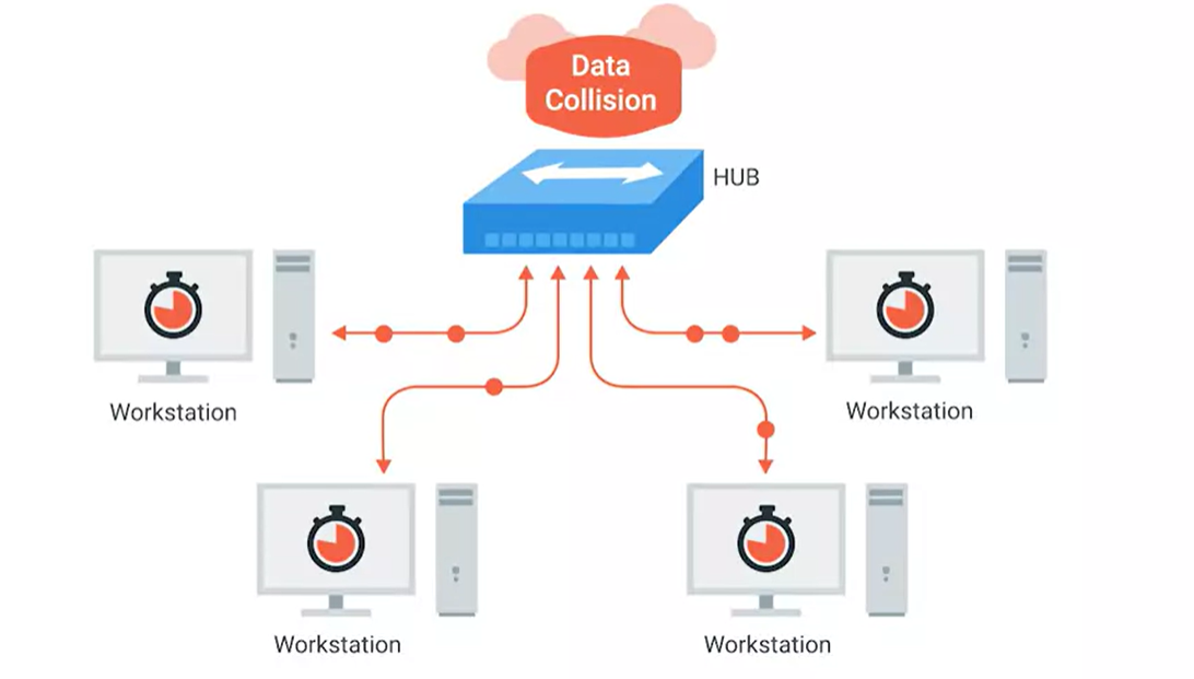
If two computers were to send data across the wire at the same time, this would result in literal collisions of the electrical current representing our ones and zeros, leaving the end result unintelligible.
Ethernet as a protocol solve this problem by using a technique known as carrier sense multiple access with collision detection.
CSMA/CD
Used to determine when the communications channels are clear, and when a device is free to transmit data.
The way CSMA/CD works is actually pretty simple. If there’s no data currently being transmitted on the network segment, a node will feel free to send data. If it turns out that two or more computers end up trying to send data at the same time, the computers detect this collision and stop sending data.
Each device involved with the collision then waits a random interval of time before trying to send data again. This random interval, helps to prevent all the computers involved in the collision from colliding again the next time they try to transmit anything.
When a network segment is a collision domain, it means that all devices on that segment receive all communication across the entire segment. This means we need a way to identify which node the transmission was actually meant for.
This is where something known as a media access control address or MAC address comes into play.
MAC address
Meaning: A globally unique identifier attached to and individual network interface.
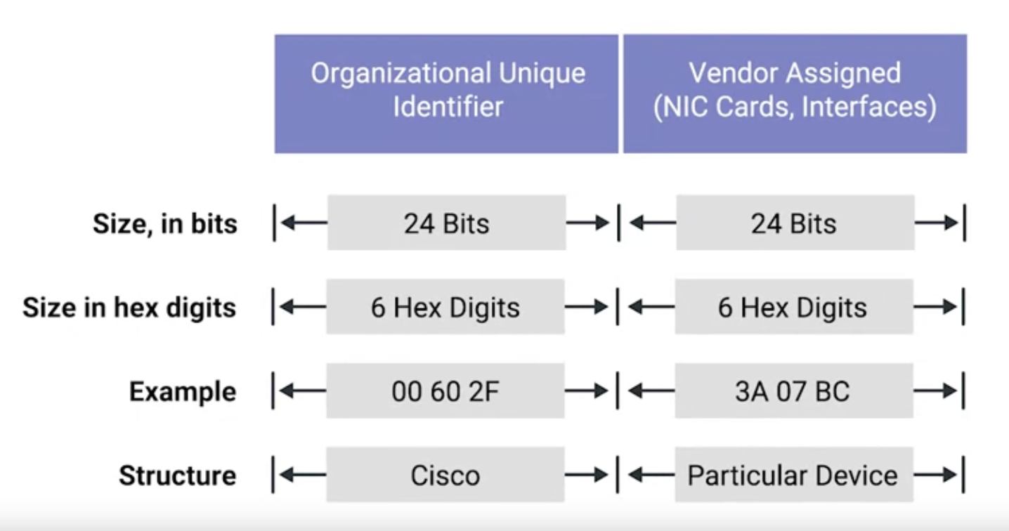
It’s a 48-bit number normally represented by six groupings of two hexadecimal numbers.
Another way to reference each group of numbers in a MAC address is an octet.
In octet, in computer networking is any number that can be represented by 8-bits. In this case, two hexdecimal digits can representsent the same numbers that 8-bits can.
A MAC address is split into two sections. The first three octets of a MAC address are known as the organizetionally unique ideatifier or OUI. These are assigned to individual hardware manufacturers by the IEEE, means that you can always identify the manufacturer of a network interface purely by its MAC address.
The last three octets of a MAC address can be assigned in any way that the manufacturer would like, with the condition that they only assign each possible address once to keep all MAC addresses globally unique.
Ethernet uses MAC addressses to ensure that the data it sends has both an address for the machine that sent the transmission, as well was, the one that the transmission was intended for. In this way, even on a network segment acting as a single collision domain, each node on that network knows when traffic is intended for it.
Types of ethernet transmission
Unicast
A unicast transmission is always meant for just one receiving address.
At the ethernet level this is done by looking at a special bit in the destination MAC address.
If the least significant bit in the first octet of a destination address is set to zero, it means that thernet frame is intended for only the destination address. This means it would be sent to all devices on the collision domain, but only actually received and processed by the intended destination.
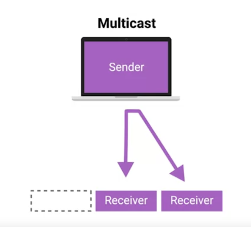
Multicast
If the least significant bit in the first octet of a destination address is set to one, it means you’re dealing with a multicast Frame.
A multicast frame is similarly set to all devices on the local network segment. What’s different is that it will be accepted or discarded by each device depending on criteria aside from their own hardware MAC address.
Broadcast
The third type of ethernet transmission is known as broadcast. In ethernet, broadcast is sent to every single device on a LAN.
This is accomplished by using a special destination known as a broadcast address. The ethernet broadcast address is all F’s: FF:FF:FF:FF:FF:FF.
Ethernet braodcasts are used so that devices can learn more about each other.
Dissecting an Ethernet Frame
Data packet
A data packet is an all-encompassing term that represents any single set of binary data being sent across a network link.
The term data packet isn’t tied to any specific layer or technology, it just represents a concept, one set of data being sent from point A to point B.
Data packets at the Ethernet level are known as Ethernet frames.
An Ethernet frame is a highly structrued collection of information presented in a specific order. This way, network interfaces at the physical layer can convert a stream of bits traveling across a link into meaningful data or vice versa.
Almost all sections of an Ethernet frame are mandatory, and most of them have a fixed size.
Preamble
The first part of an Ethernet frame is known as the preamble. A preamble is eight bytes or 64 bits long, and can itself be split into two sections.
The first seven bytes are a series of alternating ones and zeros. These act partially as a buffer between frames and can also be used by the network interfaces to synchronize internal clocks thry use to regulate the speed at which they send data.
This last byte in the preamble is known as the SFD, or start frame delimiter. This signals to a receiving device that the preamble is over and that the actual frame contents will now follow.
Desination MAC address
Immediately following the start frame delimiter, comes the destination MAC address.
This is the hardware address of the intended recipient, which is then followed by the source MAC address or where the frame originated from.
Don’t forget that each MAC address is 48 bits or six bytes long.
Ethernet frame
It’s 16 bits long and used to describe the protocol of the contents of the frame.
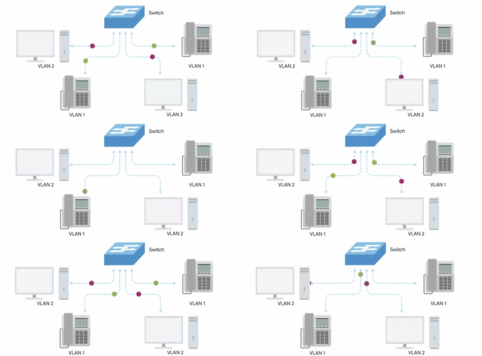
VLAN header
Indicates that the frame itself is what’s called a VLAN frame.
If a VLAN header is present, the Ethertype field follows it.
VLAN: Virtual LAN, A technique that lets you have multiple logical LANs operating on the same physical equipment.
Plyload
In networking terms, is the actual data being transported, which is everything that isn’t a header.
Frame check sequence
A 4-byte (or 32-bit) number that represents a checksum value for the entire frame.
This checksum value is calculated by perfoming what’s known as a cyclical redundancy check against the frame.
What’s next?
On an localarea network or LAN, nodes can communicate with each other through their physical MAC address. This works well on small scale because switches can quickly learn the MAC addresses connected to each other ports to four transmissions appropriately.
But MAC addressing isn’t scheme that scales well. Every single network interface on the planet has a unique MAC address, and they aren’t ordered in any systematic way. There’s no way of knowing where on the planet a certain MAC address might be at any one point in time, so it’s not ideal for communicating across distances.
Network layer
Define: Allows different networks to communicate with each other through devices known as routers.
A collection of networks connected together through routers, the most famous of these being the internet.
IP is the heart of the internet and most smaller networks worldwide.
IP addresses are a 32-bit long numbers made up of four octets and each octet is normally described in decimal numbers. Eight bits of data or a single octet can represent all decimal numbers from 0-255.
The important thing to know for now is that IP address are distributed in large sections to various organizations and companies instead of being determined by hardware vendors. This means that IP addresses are more tierarchical and easier to store data about than physical addresses are.
Think of IBM, which owns every single IP that has the Number 9 as the first octet. At a very high level, this menas that is an Internet router needs to figure out where to send a data packet intended for the IP address 90.0.0.1, that router only has to kknow to get it to one of IBM’s routers. That router can handle the rest of the delivery process from there.
Dynamic IP address
It’s imporatant to call out that IP addresses belong to the networks, not to the devices attached to those networks. Your laptop will always have the same MAC address no matter where you use it. but it’ll have a different IP address assigned to it at an Internet cafe than it would when you’re at home.
On many modern networks, you can connect a new device and an IP address will be assigned to it automatically through a technology known as DYnamic Host Configuration Protocol.
An IP address assigned this way is known as a dynamic IP address.
Static IP address
The opposite of this is knowm as a static IP address, which must be configured on a node manually. In most cases, static IP addresses are reserved for servers and network devices while dynamic IP addresses are reserved for clients.
IP datagram
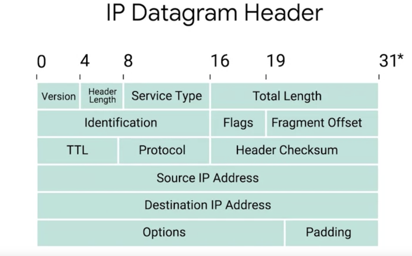
IP datagram is a highly structured series of fields that are strictly defined.
IP datagram header
The very first field is four bits and indicates what version of Internet Protocol is being used. The most common version of IP is version 4 or IPv4.
After the version field we have the header length field. This is also a four bit field that declares how long the entire header is.
Next we have the service type field, these 8 bits can be used to specify details about quality of service or QoS technologies. The important takeaway about QoS is that there are services that allow routers to make decisions about which IP datagram maybe more important than others.
The next field is a 16 bit field known as the total length field. It’s used for exactly what it sounds like to indicate the total length of the IP datagram it’s attached to.
The maximum size of a single datagram is the largest number you can represent with 16 bits. If the total amount of data that needs to be sent is larger than what can fit in a single datagram, the IP layer needs to split this data up into many individual packets.
Flag field
Used to indicate if a datagram is allowed to be fragmented, or to indicate that the datagram has already been fragmented.
Fragmentation
Is the process of taking a single IP datagram and splitting it up into several smaller datagrams.
Time to live (TTL) field
An 8-bit field that indicates how many router hops a datagram can travelse before it’s thrown away.
The main purpose of this field is to make sure that when there’s a miss configuration in routing that causes an endless loop. Datagrams don’t spend all eternity trying to reach their destination. An endless loop could be when router A thinks router B is the next hop and router B thinks router A is the net hop.
Protocol field
Another 8-bits field that contains data about what transport layer protocol is being used.
Header checksum field
A checksum of the contents of the entire IP datagram header. It’s functions very much like the ethernet checksum field.
IP options field
An optional field and is used to set special characteristics for datagrams promarily used for testing purposes.
Padding field
The IP options field is usually followed by a padding field since the IP options field is both optional and variable in length.
The padding field is just a series of zeroes used to ensure the header is the correct total size.
Address class system
A way of defining how the global IP address space is split up.
There are three types of classes:
- Class A
Class A addresses are those where the first octet is used for the network ID and the last three are used for the host ID.
- Class B
Class B addresses are where the first two octets are used for the network ID and the second two are used for the host ID.
- Class C
Class C addresses are those where the first three octets are used for the network ID and only the final octet is used for the host ID.
Address resolution protocol (ARP)
A protocol used to discover the hardware address of a node with a certain IP address.
Almost all network connected devices will retain a local ARP table. An ARP table is just a list of IP addresses and the MAC address is associated with them.
ARP table entries generally expire after a short amout of time to ensure changes in the network are accounted for.
Subnetting
The process of taking a large network and splitting it up into many individual and smaller subnetworks, or subnets.
Subnet masks
32-bit numbers that are normally written out as four octets in decimal.
Router
Router: A network device that forwards traffic depending on the destination address of that traffic.
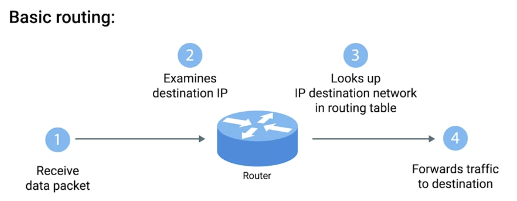
Basic routing has just a few steps.
One, a router receives a packet of data on one of its interfaces.
Two, the router examines the destination IP of this packet.
Three, the router then looks up the destination network of this IP in its routing table.
Four, the router forwards that out through the interface that’s closest to the remote network as determined by additional info within the routing table.
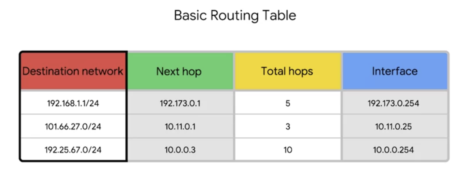
Routing table
Destination network
This column would contain a row for each network that the router knows about.
Next hop
This is the IP address of the next router that should reveive data intended for the destination networking question.
Total hops
Used for keep track of how far away that destination currently is.
Interface
The router also has to know which of its interfaces it should forward traffic, matching the destination network out of.
Routing protocols
The real magic of routing is in the way that routing tables are always updated with new information about the quickest path to destination networks.
What is routing protocols: These are special protocols, the routers use to speak to each other in order to share what information they might have.
Interior Gateway protocols
Definition: Used by routers to share information within a single autonomous system. An antonomous system is a collection of networks that all fall under the control of a single network operator.
Link state routing protocols
Routers using a link state protocol taking more sophisticated approach to determining the best path to a network.
Link state protocols get their name because each router advertises the state of the link of each of its interfaces.
These interfaces could be connected to other routers or they could be direct connections to networks.
Distance vector protocols
Distance vector protocols are an older standard.
A router using a distance vector protocol basically just takes its routing table,which is a list of every network known to it and how far away these networks are in terms of hops.
Then the router sends this list to every neighboring router which is basically
every router directly connected to it.
In computer science, a list is known as a vector.
This is why a protocol that just sends a list of distances to networks is known as a distance vector protocol.
Exterior Gateways protocols
Exterior gateway protocols are used to communicate data between routers representing the edges of an autonomous system.
Since routers sharing data using interior gateway protocols are all under control of the same organization.
Routers use exterior gateway protocols when they need to share information across different organizations.
Internet Assigned Numbers Authority (IANA)
A non-profit organization that helps manage things like IP address allocationion.
ASN: Autonomous system number, Numbers assigned to individual autonomous systems.
Transport layer
Sorts out which client and server programs are supposed to get that data.
Transport layer allows traffic to be directed to specific network applications.
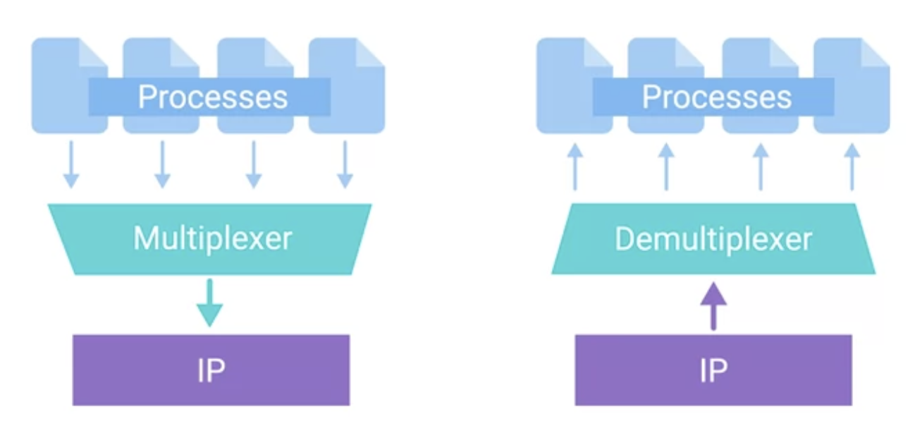
Multiplexing
Multiplexing in the transport layer means that nodes on a network have the ability to direct traffic toward many different receiving services.
Demultiplexing
Demultiplexing is the same concept just at the receiving end, it’s taking traffic that’s all aimed at the same node and delivering it to the proper receiving service.
The transport layer handles multiplexing and demultiplexing through ports.
A port is a 16-bit number that’s used to direct traffic to specific services running on a networked computer.
TCP segment: Made up of a TCP header and a data section.
Source port
Source port: A high-numbered port chosen from a special section of ports known as ephemeral ports.
A source port is needed so that when the web server replies, the computer making the original request can send this data to the program that was actually requesting it.
Sequence number: This is a 32-bit number that’s used to keep track of where in a sequence of TCP segments this one is expected to be.
Data offset field: A 4-bit number that communicates how long the TCP header for this segment is.
TCP checksum: Specifies the range of sequence numbers that might be sent before an acknowledgement is required.
Urgent pointer field: Used in conjunction with one of the TCP control flags to point out particular segments that might be more important than others.
TCP Control Flags
The way TCP establishes a connection is through the use of different TCP control flags used in a very specific order.
URG (urgent)
A value of one here indicates that the segment is considered urgent and that the urgent pointer field has more data about this.
ACK (acknowledge)
A value of one in this field means that the acknowledgement number field should be examined.
PSH (push)
The transmitting device wants the receiving device to push currently-buffered data to the application on the receiving end as soon as possible.
A buffer is a computing technique in which a certain amount of data is held somewhere before being sent elsewhere.
RST (reset)
One of the sides in a TCP connection hasn’t been able to recover from a series of missing or malformed segments properly.
SYN (synchronize)
It’s used when first establishing a TCP connection and making sure the receiving end knows how to examine the sequence number field.
FIN (finish)
When this flag is set to one, it means the transmitting computer doesn’t have any more data to send and the connection can be closed.
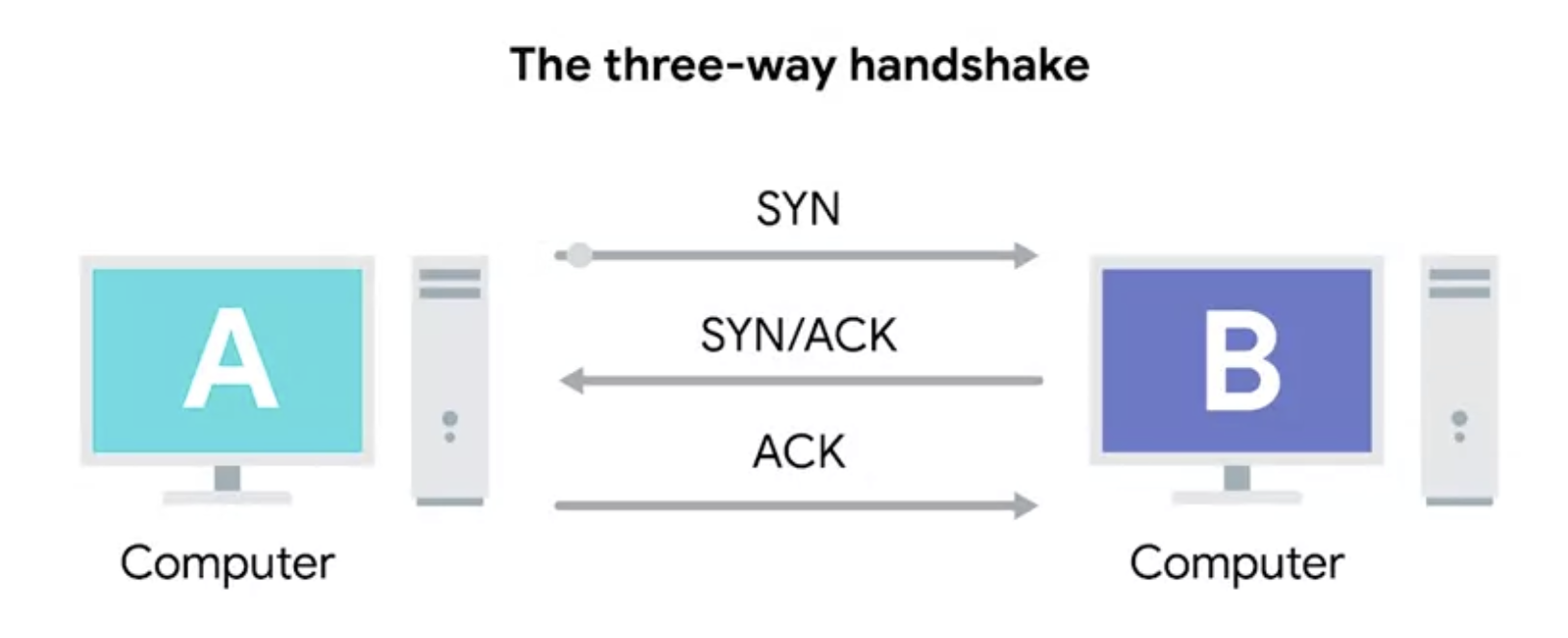
The three-way handshake
A handshake is a way for two devices to ensure that they’re speaking the same protocol and will be able to understand each other.
Computer A will be our transmitting computer, and computer B will be our receiving computer.
First, to start the process off, Computer A sends a TCP segment to Computer B, with a SYN flag sent. This is computer A’s way of saying, let’s establish a connection and look at my sequence number field so we know where this conversation starts. Second, Computer B then responds with a TCP segment where both the SYN and ACK flags are sent. This is computer B’s way of saying, sure, let’s establish a connection, and I acknowledge your sequence number.
Last, Computer A responds again with just the ACK flag sent, which is just saying I acknowledge your acknowledgement. Let’s start sending data.
Once the three-way handshake is complete, the TCP connection is established
Now, computer A is free to send whatever data it wants to computer B and vice versa.
Since both sides have now sent SYN/ACK pairs to each other, a TCP connection in this state is operating in full duplex.
Each segment sent in either direction should be responded to by a TCP segment with the ACK field sent. This way the other side always knows what has been received.
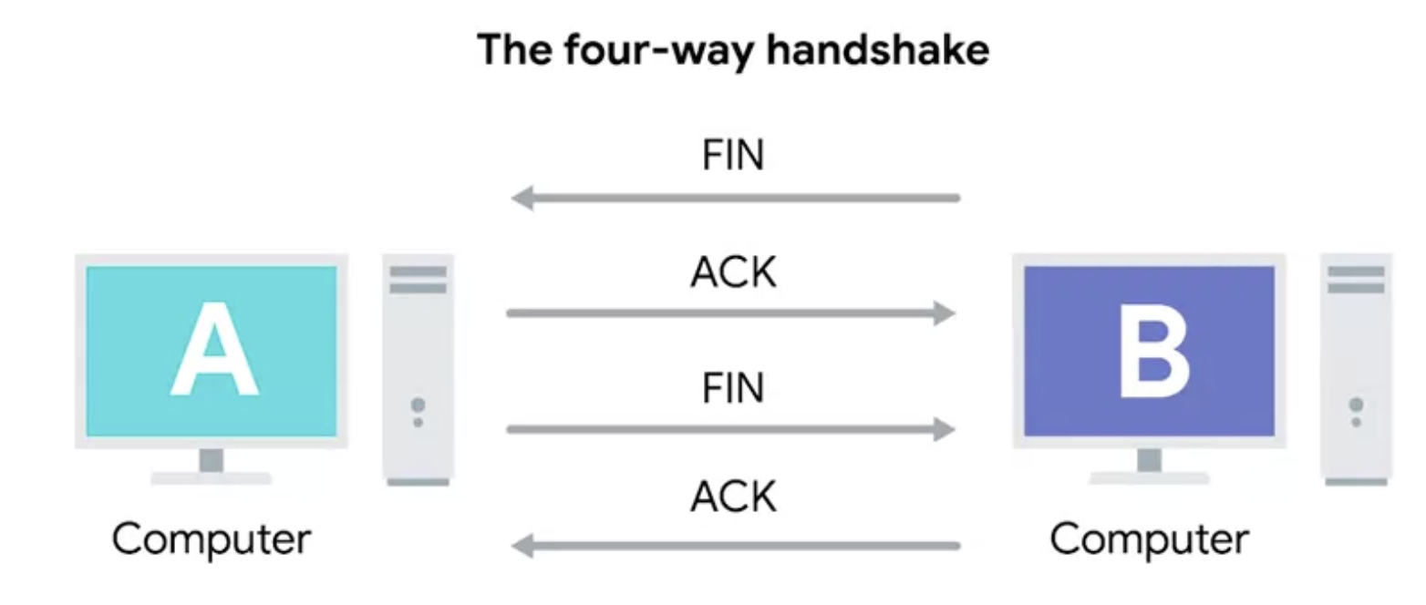
Once one of the devices involved with the TCP conncetion is ready to close the connection, something known as a four-way handshake happens.
The four-way handshake
The computer ready to close the connection sends a FIN flag, which the other computer acknowledges with an ACK flag.
Then, if this computer is also ready to close the connection, which will almost always be the case, it will send a FIN flag.
This is again responded to by an ACK flag.
TCP Socket States
A socket is the instantiation of an endpoint in a potential TCP connection.
An instantiation is the actual implementation of something defined elsewhere.
You can send traffic to any ports you want, but you’re only going to get a response if a program has opened a socket on that port.
LISTEN
Listen means that a TCP socket is ready and listening for incoming connections. You’ll see this only on the server side.
SYN_SENT
This means that a synchronization request has been sent, but the connection hasn’t been established yet. You’d see this only on the client side.
SYN-RECEIVED
A socket previously in a LISTEN state has received a synchronization request and sent a SYN/ACK back, but the client hasn’t yet received the final ACK. You’d see this only on the server side.
ESTABLISHED
This means that the TCP connection is in working order, and both sides are free to send each other data. You’d see this state on both the client and server side of a connection.
FIN_WAIT
A FIN has been sent, but the corresponding ACK from the other end hasn’t been received yet.
CLOSE_WAIT
This means that the connection has been closed at the TCP layer, but that the application that opened the socked hasn’t released its hold on the socket yet.
CLOSED
This means that the connection has been fully terminated and that no further communication is possible.
Connection-oriented and Connectionless Protocols
A connection-oriented protocol is one that establishes a connection and uses this to ensure that all data has been properly transmitted.
Once a TCP segment tells a service to listen for requests through a port, that listening port becomes a “socket.” In other words, a socket is an active port used by a service. Once a socket is activated, a client can send and receive data through it.
While TCP will generally send all segments in sequential order, they may not always arrive in that order. If some of the segments had to be resent due to errors at lower layers, it doesn’t matter if they arrive slightly out of order.
This is because sequence numbers allow for all of the data to be put back together in the right order.
Network services are run by listening to specific ports for incoming data requests.
- Ports are represented by a single 16-bit number (65535 different port ids)
- Ports are split up by the IANA (Internet Assigned Numbers Authority) into three categories: System Ports (ports 1-1023), User Ports (ports 1024-49151), and Ephemeral (Dynamic) Ports (ports 49152-65535).
- A socket is a port that a TCP segment has activated to listen for data requests.
- Ports allow services to send data to your computer but can also send malware into a client program. It’s important to secure your ports.
UDP-connectionless protocols
UDP: User Datagram Protocol.
Unlike TCP, UDP doesn’t rely on connections, and it doesn’t even support the concept of an acknowledgement.
With UDP, you just set a destination port and send the packet. This is useful for messages that aren’t super important, such as UDP, when streaming video.
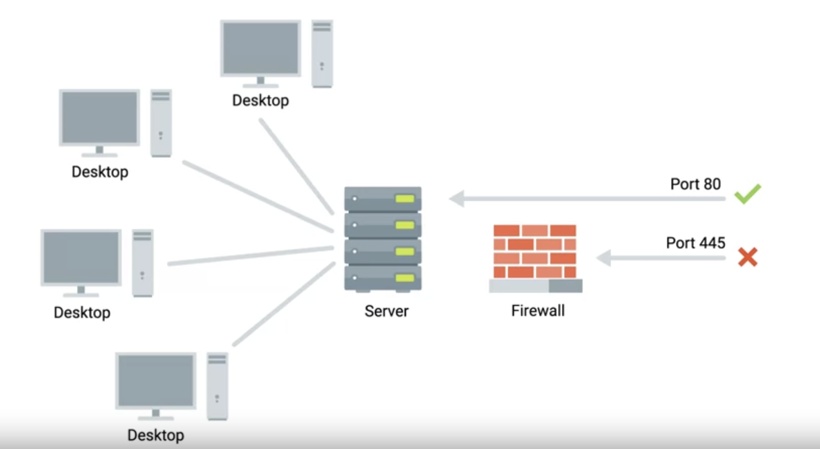
Firewalls
A firewall is a device that blocks traffic that meets certain criteria.
Firewalls that operate at the transportation layer will generally have a configuration that enables them to block traffic to certain ports while allowing traffic to other ports.
Application layer
There are lots of different protocols at this level; they’re application-specific.
The application layer allows applications to communicate in a way they understand.
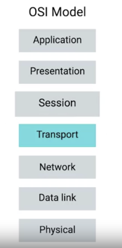
OSI Model
The OSI model has seven layers and introduces two additional layers between our transport and application layers.
The fifth layer in the OSI model is the session layer.
The concept of the session layer is that it’s responsible for things like facilitating the communication between actual applications and the transport layer. Takes application layer data and hands it off to the presentation layer.
The sixth layer: Presentation layer.
The presentation layer is responsible for ensuring that the unencapsulated application layer data can be understood by the application in question. This is the part of an operating system that might handle encryption or compression of data.
Package being delivered
You can think of layers like different aspects of a package being delivered.
The physical layer is the delivery truck and the roads.
The data link layer is how the delivery trucks get from one intersection to the next over and over.
The network layer identifies which roads need to be taken to get from address A to Address B.
The transport layer ensures the delivery driver knows how to knock on your door to tell you your package has arrived.
The application layer is the contents of the package itself.
Transport
Cables: Connect different devices to each other, allowing data to be transmitted over them.
Most network cables used today can be split into two categories:
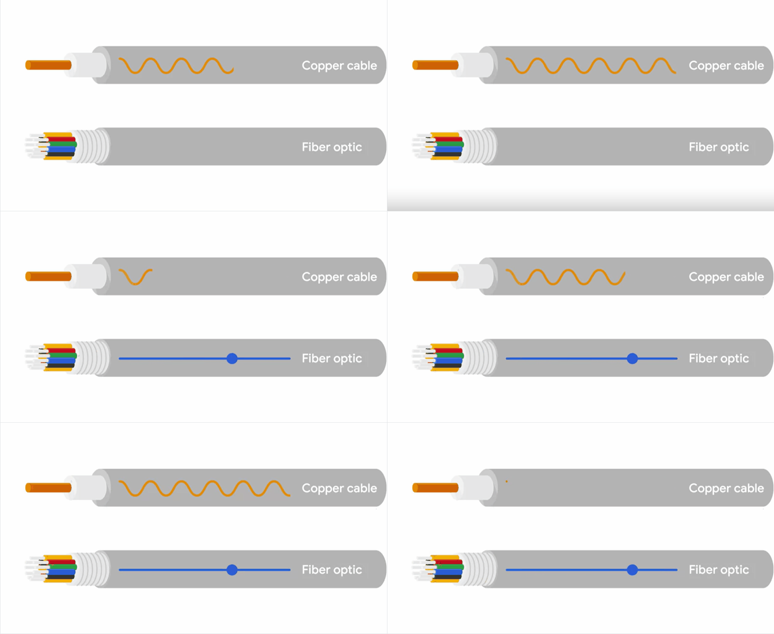
copper
Copper cables are the most common form of networking cable.
They’re made up of multiple pairs of copper wires inside plastic insulators.
The sending device communicates binary data across these copper wires by changing the voltage between two ranges.
The system at the receiving end is able to interpret these voltage changes as binary ones and zeros, which can then be translated into different forms of data.
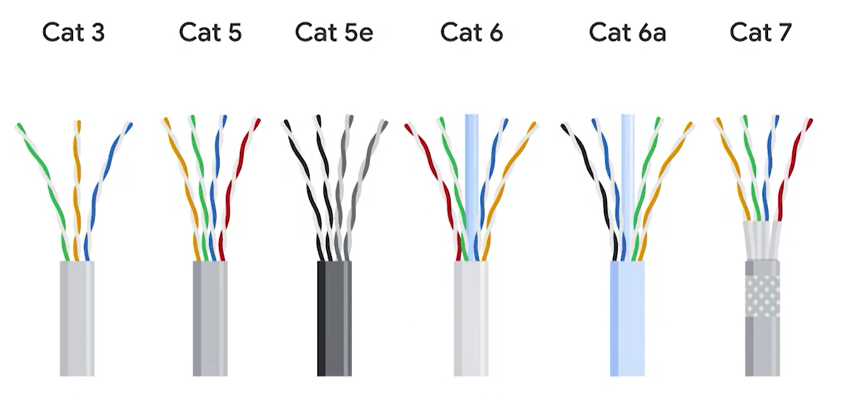
The most common forms of copper twisted-pair cables used in networking are Cat5, Cat5e, and Cat6 cables.
Cat5e cables have mostly replaced those older Cat5 cables because their internals reduce Crosstalk. **Crosstalk **is when an electrical pulse on one wire is accidentally detected on another wire. So the receiving end can’t understand the data causing a network error.
fiber
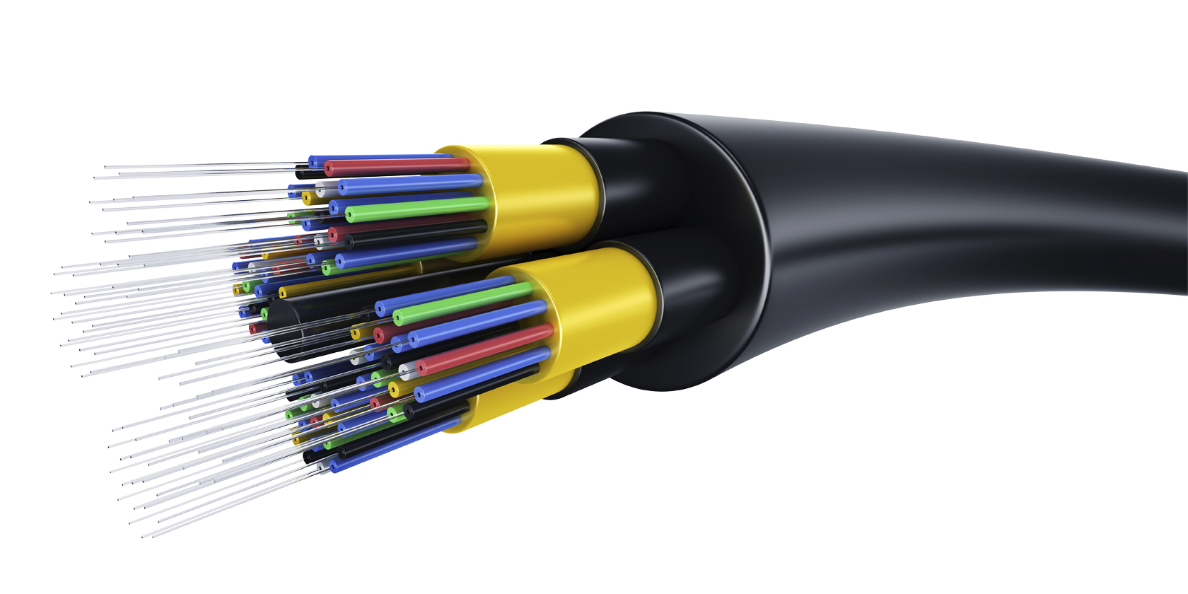
Fibre cables contain individual optical fibres, which are tiny tubes made out of glass about the width of human hair.
Unlike copper, which uses electrical voltages, fiber cables use pulses of light to represent the ones and zeros of the underlying data.
Fiber cables can generally transport data quicker than copper cables can, but they’re much more expensive and fragile.
FIber can also transport data over much longer distances than copper can without suffering potential data loss.
Hub
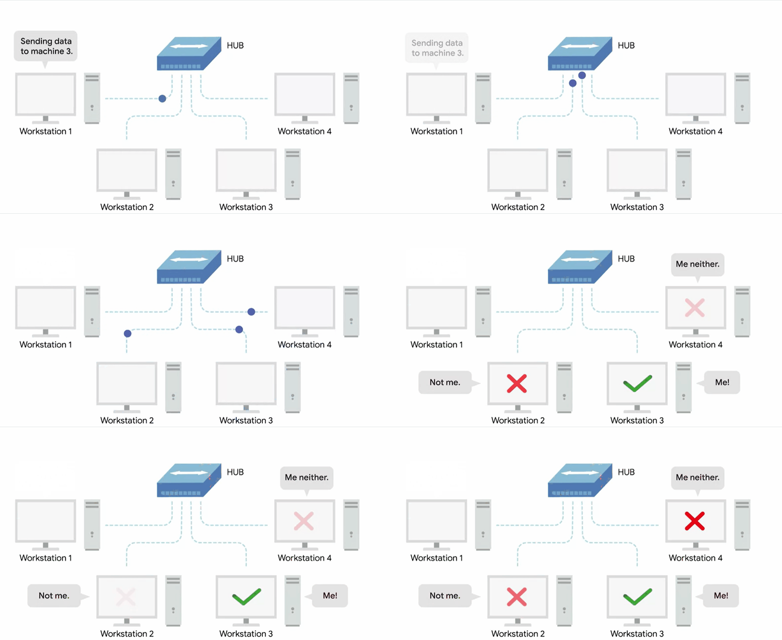
A hub is a physical layer device allowing for connections from many computers simultaneously.
All the devices connected to a hub will end up talking to all other devices at the same time.
It’s up to each system connected to the hub to determine if the incoming data was meant for them or to ignore it if it isn’t. This causes a lot of noise on the network and creates what’s called a collision domain.
A collision domain is a network segment where only one device can communicate at a time.
Network switch
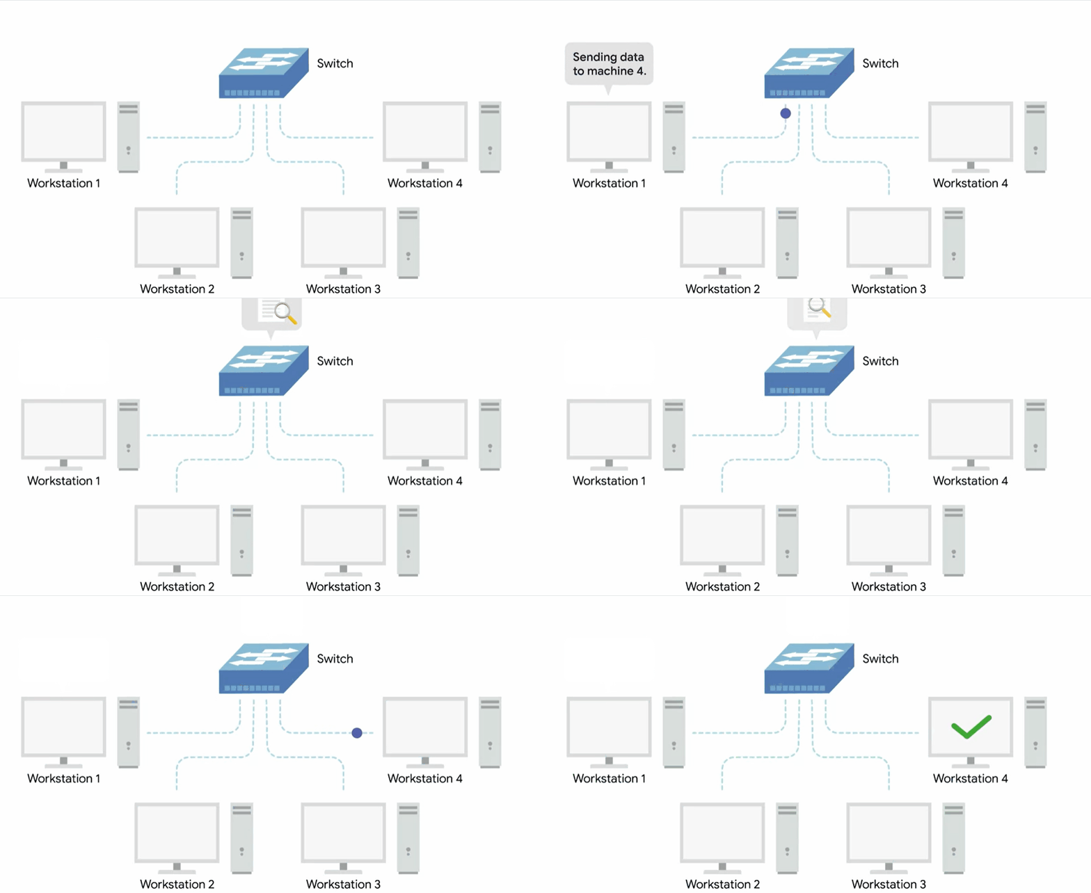
Since the hub is really slowing down network communications and is the primary reason hubs are rare. A much more common way of connecting many computers is with a more sophisticated device known as a network switch.
A switch is very similar to a hub since you can connect many devices to it so they can communicate.
The difference is that while a hub is a layer one or physical layer device, a switch is a layer two or data link device.
This means that a switch can inspect the contents of the ethernet protocol data being sent around the network, determine which system the data is intended for and then only send that data to that one system.
This reduces or even completely eliminates the size of collision domains on a network.
Routers
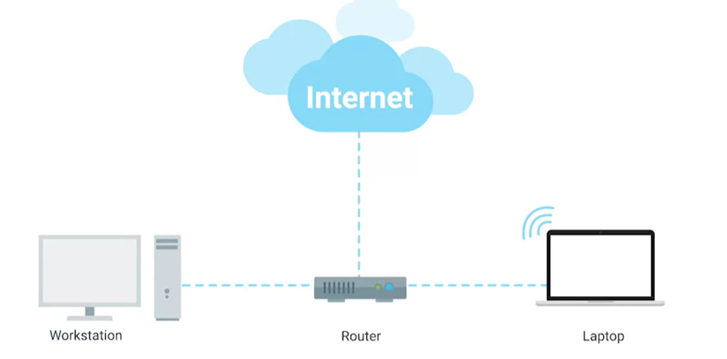
Hubs and switches are the primary devices used to connect computers on a single network, usually referred to as a LAN or a Local Area Network. But we often want to send or receive data to computers on other networks. This is where routers come into play.
A router is a device that knows how to forward data between independent networks.
- A hub is a layer one device, and a switch is a layer two device.
- A router operates at layer three, a network layer.
Just like a switch can inspect Ethernet data to determine where to send things, a router can inspect IP data to determine where to send things. Routers store internal tables containing information about how to route traffic between lots of different networks all over the world.
A core router usually has many different connections to many other routers. Routers share data with each other via a protocol known as BGP or Border Gateway Protocol. That lets them learn about the most optimal paths to forward traffic.
The internet is incredibly large and complicated, and routers are global guides for getting traffic to the right places.
Severs and Clients
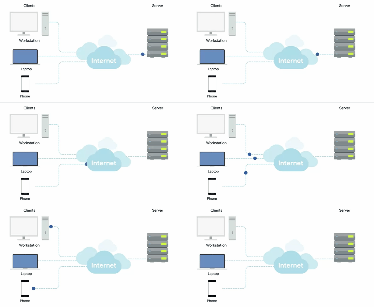
A server is something that provides data to something requesting that data.
The thing receiving the data is referred to as a client.

